

BACKGROUND
The UAV initiatives at T-Works started with the objective of providing the growing UAV community with resources in the form of research documents and prototypes of UAVs, UAV components, and sub-components. Our initial projects were designing and developing different categories of UAVs using 3D printing as the primary fabrication technique. This opened up possibilities of using 3D printed parts not only for rapid prototyping but also on final products.
MEDICINE FROM THE SKY
The Telangana Government and World Economic Forum announced the “Medicine From The Sky” initiative in 2020. The essence of this project is expeditious delivery of essential medical supplies via Unmanned Aerial Systems or drones, as we commonly call them. In June 2021, the Indian Council of Medical Research (ICMR) invited bids to deliver medical supplies and vaccines by drones.
Although not a new concept, such a facility is not yet available in India. Zipline, a California-based company, has successfully conducted drone medical payload delivery in different parts of Africa in collaboration with the government there.

Zipline’s Medical Payload Delivery UAV
IDEATION
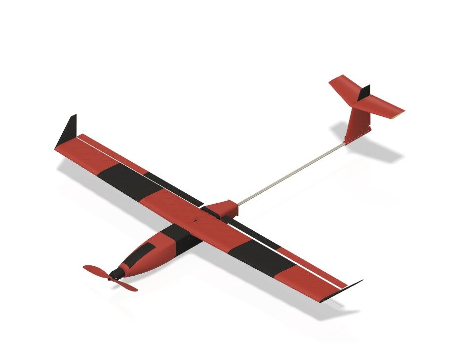
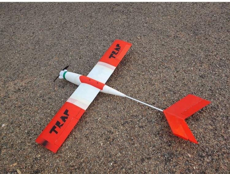
At the time we were doing our R&D on fixed-wing drones, rapidly making multiple UAVs using 3D printing, Medicine from the Sky gave us target parameters to work on.
We identified that the key in achieving the range and speed required for faster and farther deliveries was building a fixed-wing UAV. Still, these deliveries would mostly be in locations that may not have runways to land a traditional fixed-wing craft. We hence decided to design a hybrid VTOL UAV - an aircraft that can take-off and land vertically like a multirotor and fly forward like a fixed-wing using both gasoline and battery power.

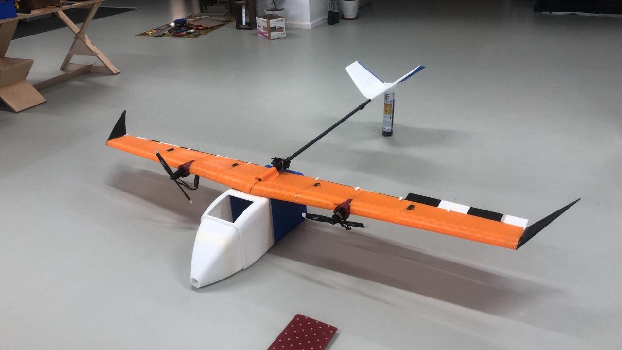
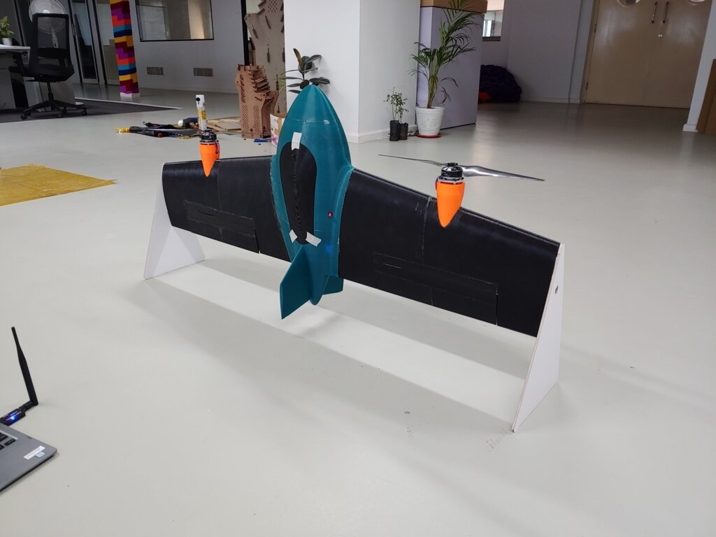
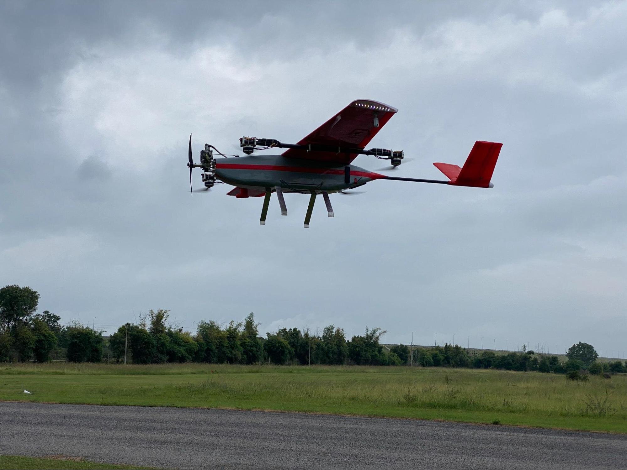
Hybrid VTOL UAV - AMRT-25
DESIGN
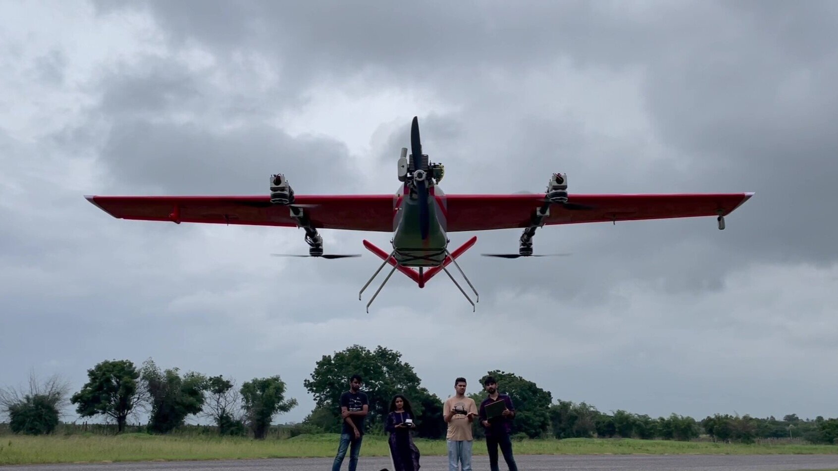
The hybrid VTOL UAV we designed, has four fixed BLDC motors for vertical take-off and landing and a 2-stroke, 30cc, gasoline-powered internal combustion (IC) engine for forward flight. We called this aircraft AMRT-25 - the 25 denotes its 2.5 m wingspan.
AMRT-25 is a versatile UAV design that can be configured to be used for medical supplies delivery as well as for survey and mapping, aerial inspection, surveillance, reconnaissance, and research applications.
TECHNICAL SPECIFICATIONS
AMRT-25 is categorized as a separate Lift - Thrust (SLT) hybrid VTOL. The power required to run the motors that lift and lower the aircraft comes from a 10,000 mAh lithium polymer battery. A 2-stroke gasoline engine was selected for its efficiency and power specifications. As mentioned earlier, faster and farther were our key targets. A 1000 cc fuel tank holds the fuel required to travel about 45-50 km in a straight line in approximately 30 minutes.
Configuration: Hybrid VTOL
Wingspan: 2.5 m
Length: 1.9 m
MTOW: 14.5 kg
Payload Weight: 1 kg
Powerplant (Fixed WIng): 30 cc Gasoline Engine
Fuel Volume: 1 litre
Powerplant (VTOL): BLDC Motors
Battery Capacity: 10 Ah 6S + 7 Ah 2S
Endurance: Upto 33 Minutes
Max. Operating Altitude: 1000 m AGL within 3000 m (~10,000 ft) AMSL
Take-off/ Landing Area: 5 m X 5 m
Telemetry & Radio Control: 868 MHz or 2.4 GHz options
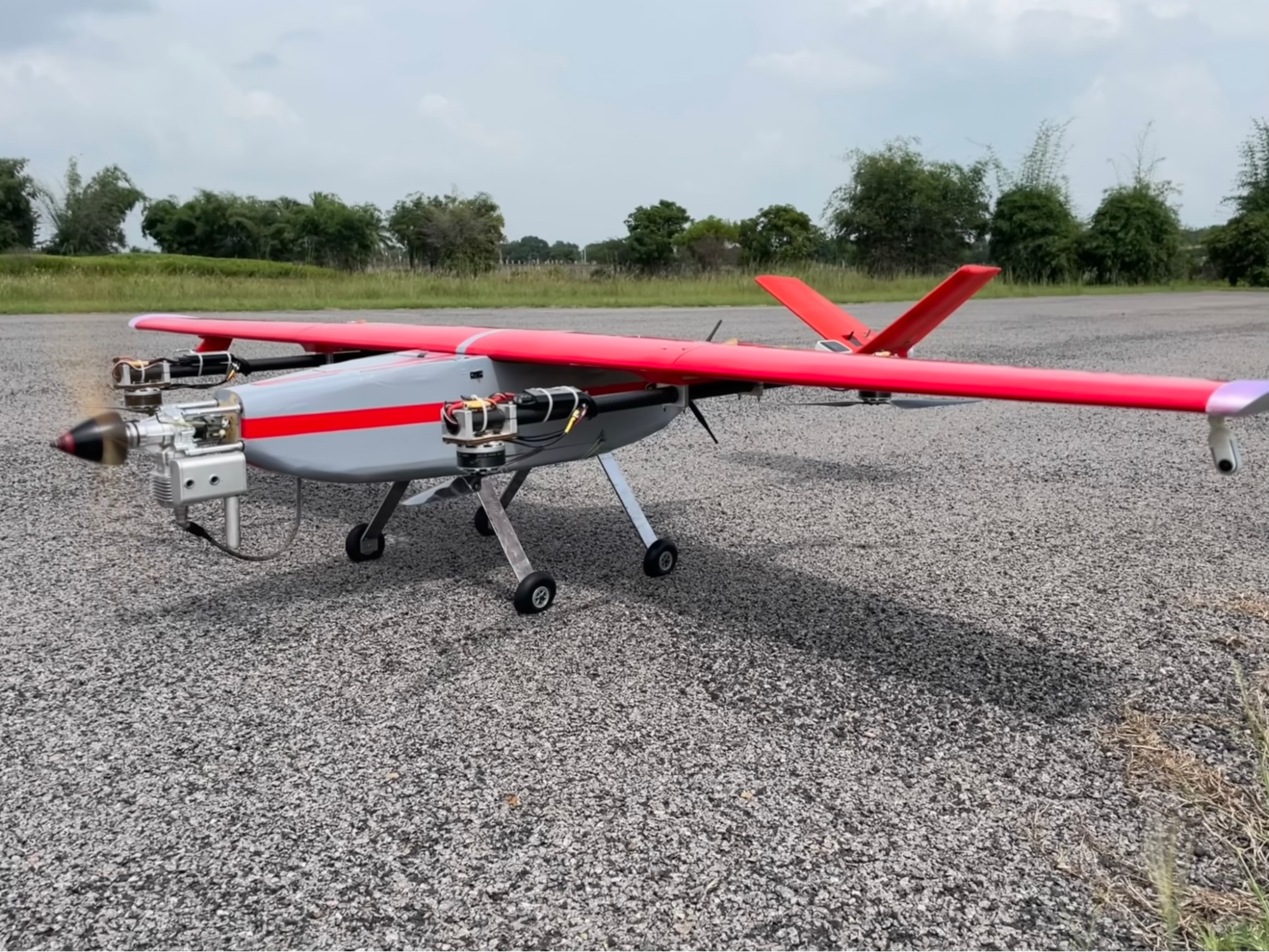
DESIGN FEATURES
The priorities were ease-of-use and deployment, faster turn-around time, scalability to different sizes, and flexibility in choosing the payload type. We spent more time on the design to minimise the fabrication time and effort. Thanks to our in-house 3D printer, CNC router and laser cutter, we could fabricate the entire craft out of our Phase-0 office in Begumpet.
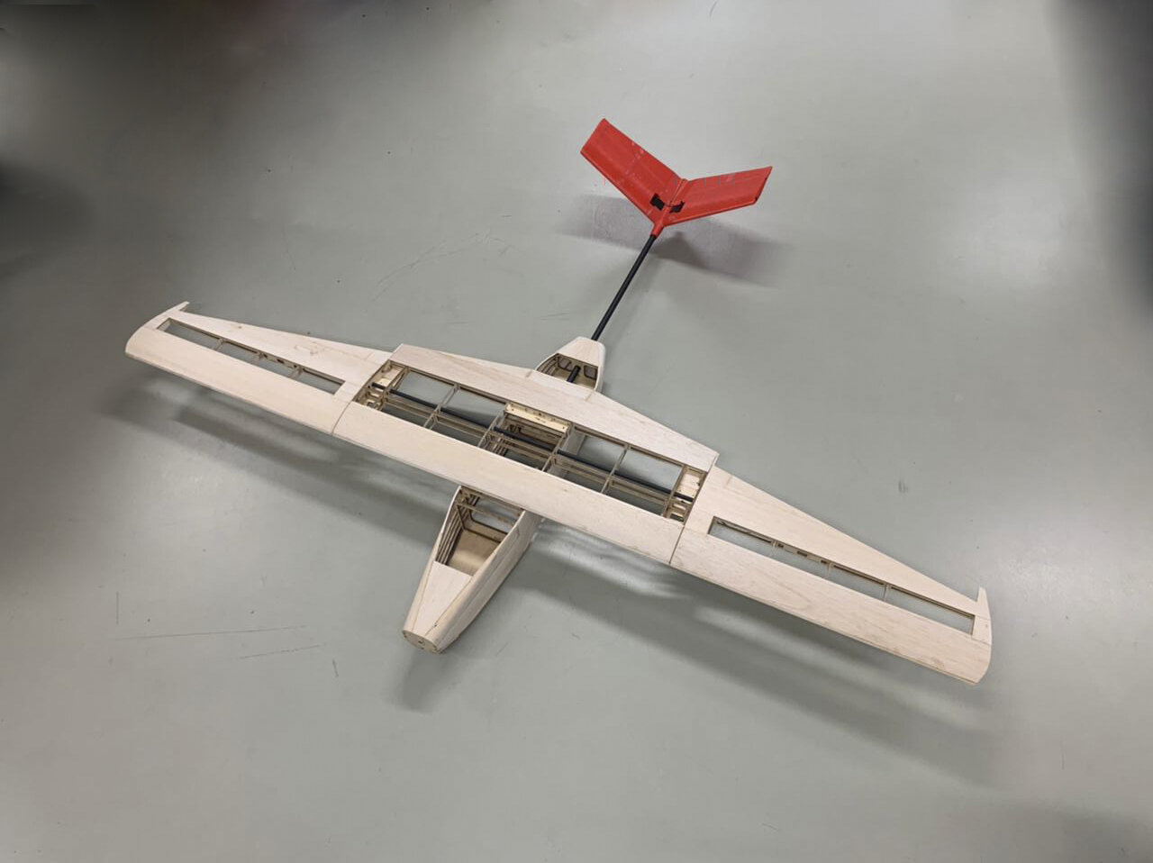

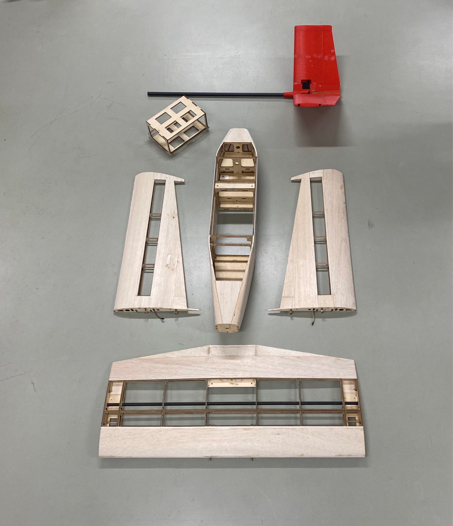
Balsa wood, light-plywood (Aero-Ply), carbon fibre tubes, and aluminium constituted the primary fabrication material. The fuselage was designed to contain electronic components, a fuel tank, and batteries. The engine was mounted in a tractor configuration - the engine and propeller mounted on the aircraft’s nose so that it is "pulled" through the air. The 3-D Printed V-tail is connected to the fuselage with a carbon fibre (CF) tail-boom. The fuselage also contains a secondary payload bay between the two aluminium landing gears which can be used to mount Electro-Optical/Infra-Red (EO/IR) or survey-grade cameras. The 3-piece wing is mounted in a high-wing configuration - on top of the aircraft’s body, adding to the aircraft’s stability. The centre section of the wing is bolted onto the fuselage. The VTOL booms, which are mounted with the BLDC Motors, are bolted to the tips of the centre section. The left and right sides of the wing are held by CF wing tubes that slide into both the side wing and the centre wing. A quick-release mechanism was designed to lock the wings laterally. The centre wing is mounted with a 3-D printed primary payload bay on the top that houses the medical payload and is easy to access.

Quick Release Wing Lateral Locking Mechanism
TEST FLIGHTS
The onboard autopilot is a Cube Orange, an open-source UAV Autopilot with triple redundant IMU (Inertial Measurement Unit) and ADS-B (Automatic Dependent Surveillance-Broadcast) support. Configuration, multiple ground tests, re-configuration, tuning flights, and test flights were conducted to ensure the mission capability of the entire system. Some of the early flight tests were:
VTOL Test in semi-autonomous mode with the engine not running
VTOL Test in semi-autonomous mode with the engine running on idle
Autonomous VTOL take-off and landing
VTOL take-off and transition in semi-autonomous modes
VTOL take-off and transition in autonomous mode
Return to Launch (RTL) test
Endurance Test
Range Test
Payload Test


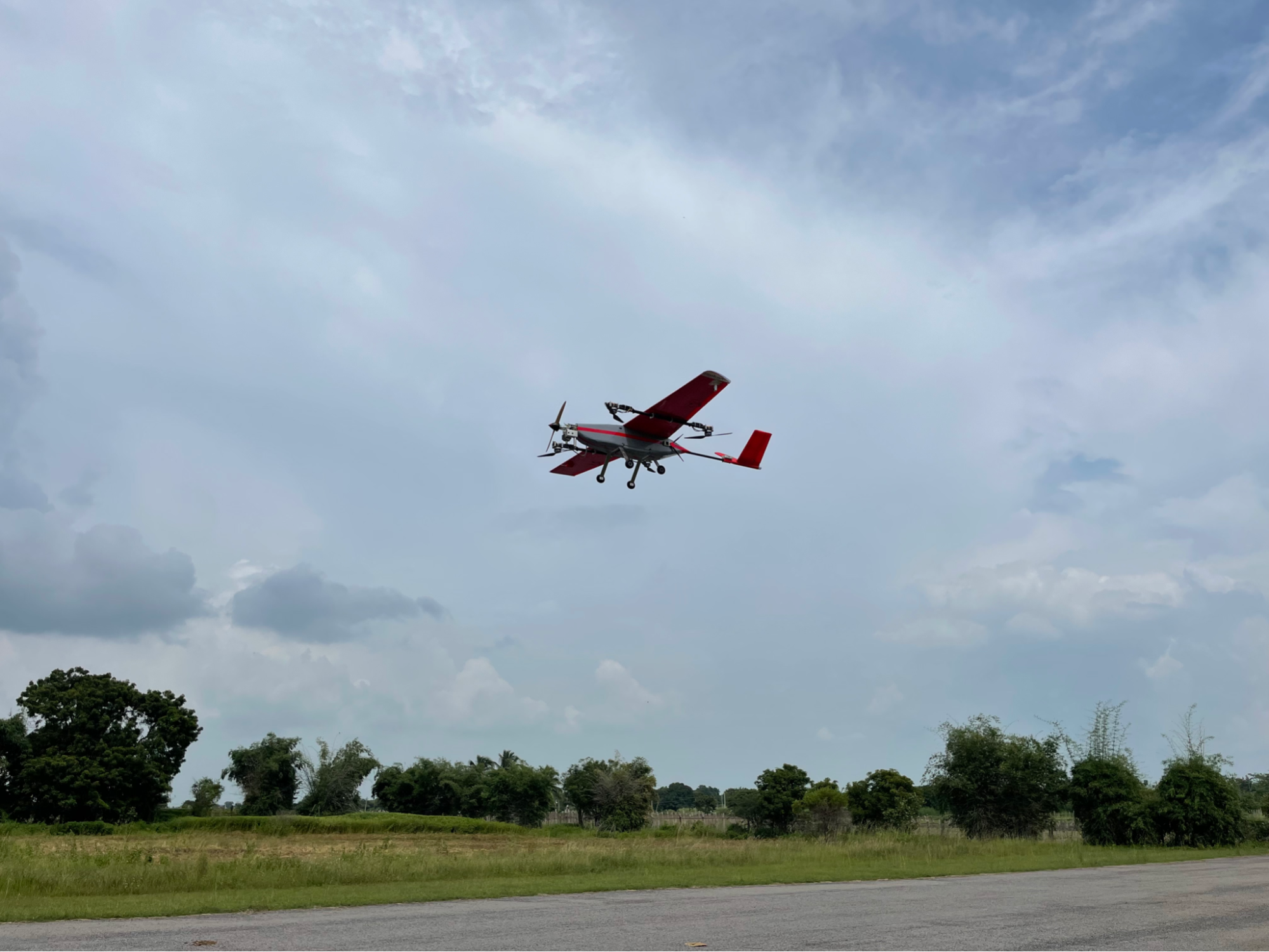


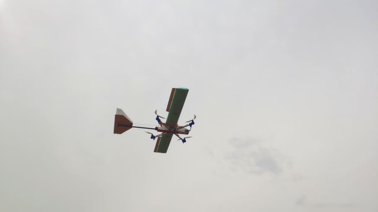
AMRT-25 successfully executing a complete autonomous waypoint mission from Takeoff to Landing.
AMRT-25 successfully executing an autonomous mission to test endurance.
Flight time: 33 minutes
Total Distance flown: 45 km
Part 1 of 2
CHALLENGES
We came across many challenges and failures before we could successfully conduct autonomous missions on the AMRT-25. Initially, the BLDC motors used were underpowered as the final weight of the aircraft surpassed our initial calculations and estimations.
The causes for the increased weight were -
Replaced:
engine (20cc was changed to 30cc)
VTOL powerplant (larger motors, ESCs, and propellers were installed)
fuel tank (500 ml tank was replaced with 1,000 ml)
battery (6000 mAh battery was changed to 10,000 mAh)
BECs (Higher Ampere BECs installed)
The wiring harness was upgraded with higher gauge wires
Reinforcements were added to the structure to accommodate heavier components
The 16” carbon fibre propellers used were flexing and stalling, which caused a lot of vibrations and could not generate enough lift. The overloaded motors also caused a substantial dip in the battery voltage, making the aircraft descend even at full power. We upgraded the propellers, motors, ESCs, and battery (essentially the entire VTOL power plant!), and we succeeded in finding and integrating the right combination.

Motor oscillations caused due to stalling propeller seen in slow-motion
The next challenge was with the engine. These single-cylinder 2-stroke engines are mainly designed for hobby use and also find applications in agricultural pumps and chainsaws - places where vibration is not a concern. But when you introduce an autopilot with a very sensitive IMU to these vibrations, the aircraft won’t listen to you. To dampen the vibration to the autopilot, we used foam mounts and failed. We used off-the-shelf vibration-dampening mounts, but those were not effective either. Finally, we 3-D printed different designs of mounts, and one particular design worked amazingly well. The vibrations recorded by the autopilot went down by 80%, and it started cooperating with us.
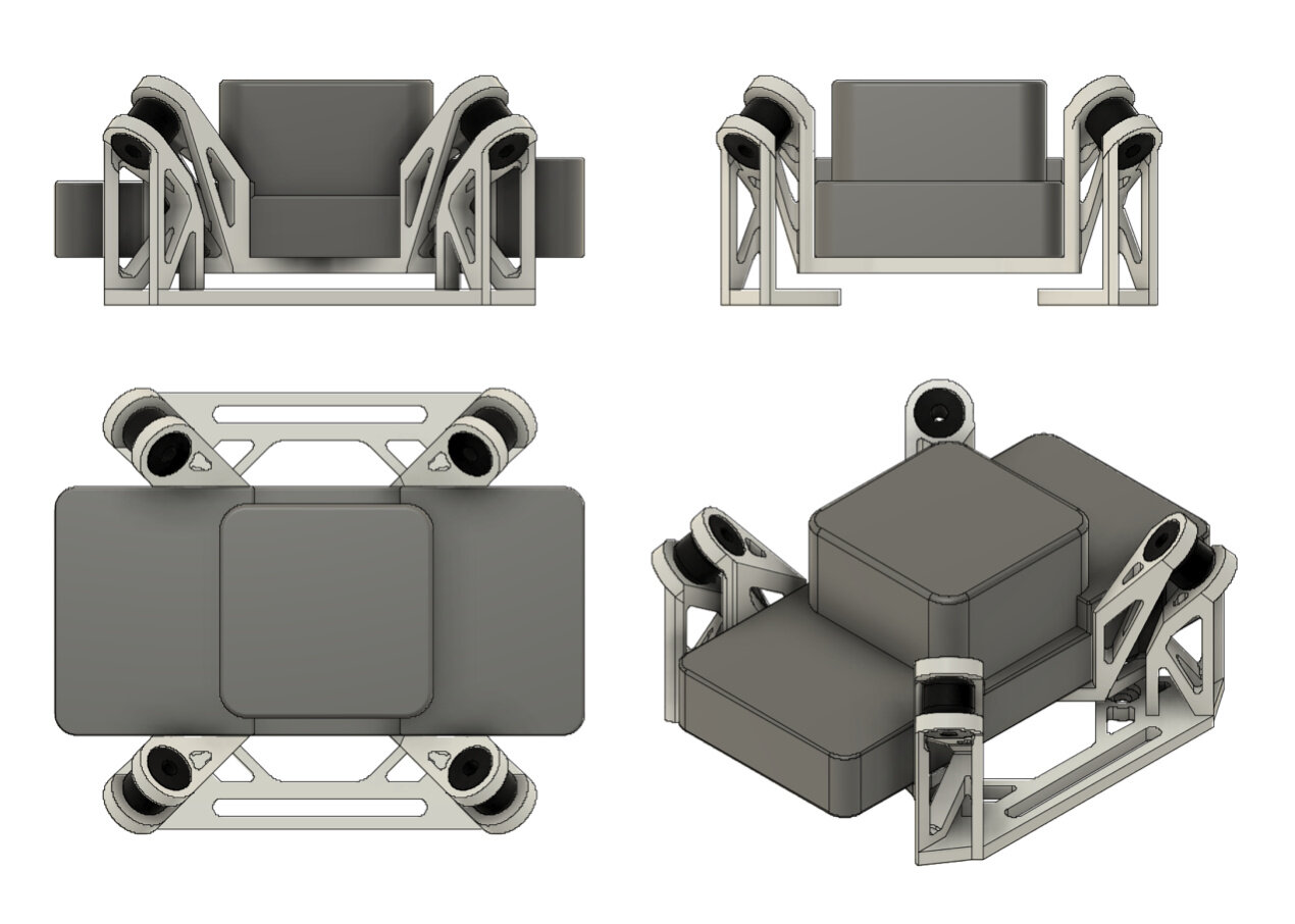
3D Printed Vibration Isolation Mount for the Cube Autopilot
The final challenge was the infamous compass variance error. We tried different routing methods and positions for the wiring and electronics. The autopilot and external compass were separated from all significant Electro-Magnetic Interference (EMI) sources such as batteries, BECs, heavy gauge wires, communication modules, and antennae by at least 15 cm. This reduced the magnetic field variations.
FUTURE
Future upgrades to the AMRT platform include but are not limited to:
Onboard Engine Starter.
4G communication module for telemetry and control
Optimized quick-release mechanisms for hatches and all detachable parts
A scaled-up variant to achieve 100 km range with 3.5 kg payload capacity (payload weight can be increased by reducing fuel weight carried)
For more information, write to us on hello@tworks.in